
Containment wall
The Containment Module (hereinafter MC®) is a prefabricated piece made of reinforced concrete in the form of “L”, whose long section has a rough finish and serves as support for the piece.
Its placement is carried out on a previously leveled esplanade that will serve as support, providing the appropriate connections between pieces on the sides of them. Subsequently, we proceed to the filling by compacted layers until reaching the required level. The slope that forms will have its foot resting on the top of the MC® wall.
The operation of the MC® is automatic, that is, the more thrust the ground exerts on it, the greater the stabilizing friction with the support that is generated at its base. In addition, its own weight contributes to the stability of the whole.
This product is protected by Spanish patent ES2386787 with international extension PCT/ES2012/000016.

Design of systems and structures for land containment
DIMENSIONS
Types and measures of the Containment Module
The dimensions of the MC® are variable: they are manufactured in two thicknesses of 15 and 20 cm. For each thickness if we call “B” the support base and “H” the height of the wall (both exterior measures), any piece can be manufactured by combining the following series:
B = 100, 125, 150, 175, 200, 225 and 250 cm.
H = 60, 75, 90, 105, 120, 135, 150, 165 and 180 cm.
Two frames are accompanied where the most recommended range of measures for each thickness appears.

For each action we will have to choose some dimensions for the MC® or a combination of them to adapt and deal with a series of variables such as: the height of existing land, the slope to be considered, the permanent or traffic loads acting, the parameters of the geotechnical landfill and underlying soil, etc.
Normally the pieces will be straight and will have a length “L” of 240 cm according to the direction of advance of the wall that is formed. It is also possible to manufacture them with a length of 120 cm.
Likewise, the MC® can be manufactured with a trapezoidal plant to be able to accompany the curve in a more optimal way in the case where the center of curvature is located at the back of the wall. We have three possibilities for the manufacture of curved parts depending on the radius that we want to achieve in the wall: setbacks of 10, 20 and 30 cm give radios of 9.40, 14.00 and 27.80 m. (See attached figure).
In each case we will choose the appropriate dimensions to arrive at an optimal solution at the technical and economic level applicable to a specific situation through the appropriate calculations.
NOMENCLATURE
The MC® will be named as follows:
MC®TRBHSLXOCL-N where we have the following:
T = Thickness that can be 15 or 20 in cm.
R = Reinforcing the piece that can be L (Light), M (Medium) and S (Strong).
B and H = base and height of the piece in cm.
S or CRV = depending if the piece is straight or curved.
L = piece length in cm: 240/120.
X/G/A = in the case that the piece is prepared for vertical connection / G idem for connection with Geogrid / A idem connection anchor.
OCL-N = OCL is the reference of a specific work and N is the number of the piece within each work.
We give two examples to clarify the designation of the pieces.

MC®15S150X90SL120GOD3-17 = Module of 15 cm thickness / Strong assembly / base of 150 cm and height of 90 cm / Straight / Length 120 cm / Prepared geogrid connection / Work OD3 piece No. 17.
MC®20M200X120CRV30L240VOA2-3 = Module of 20 cm thickness / Medium assembly / 200 cm base and 120 cm height / Reverse curve 30 / Length 240 cm / Prepared vertical connection / Work OA2 piece No. 3.
With the Containment Module we solve a wide variety of situations that arise in the field of Civil Engineering and Mitlan’s team offers to study together with the client all possible alternatives. In other words, if we can “imagine” a solution, we can then draw it and “test it” with the help of the appropriate software held by Mitlan and according to the results we will weigh the convenience of the action. Mitlan owns PLAXIS 2D 2019 and CivilFEM for Marc Advanced 2019.

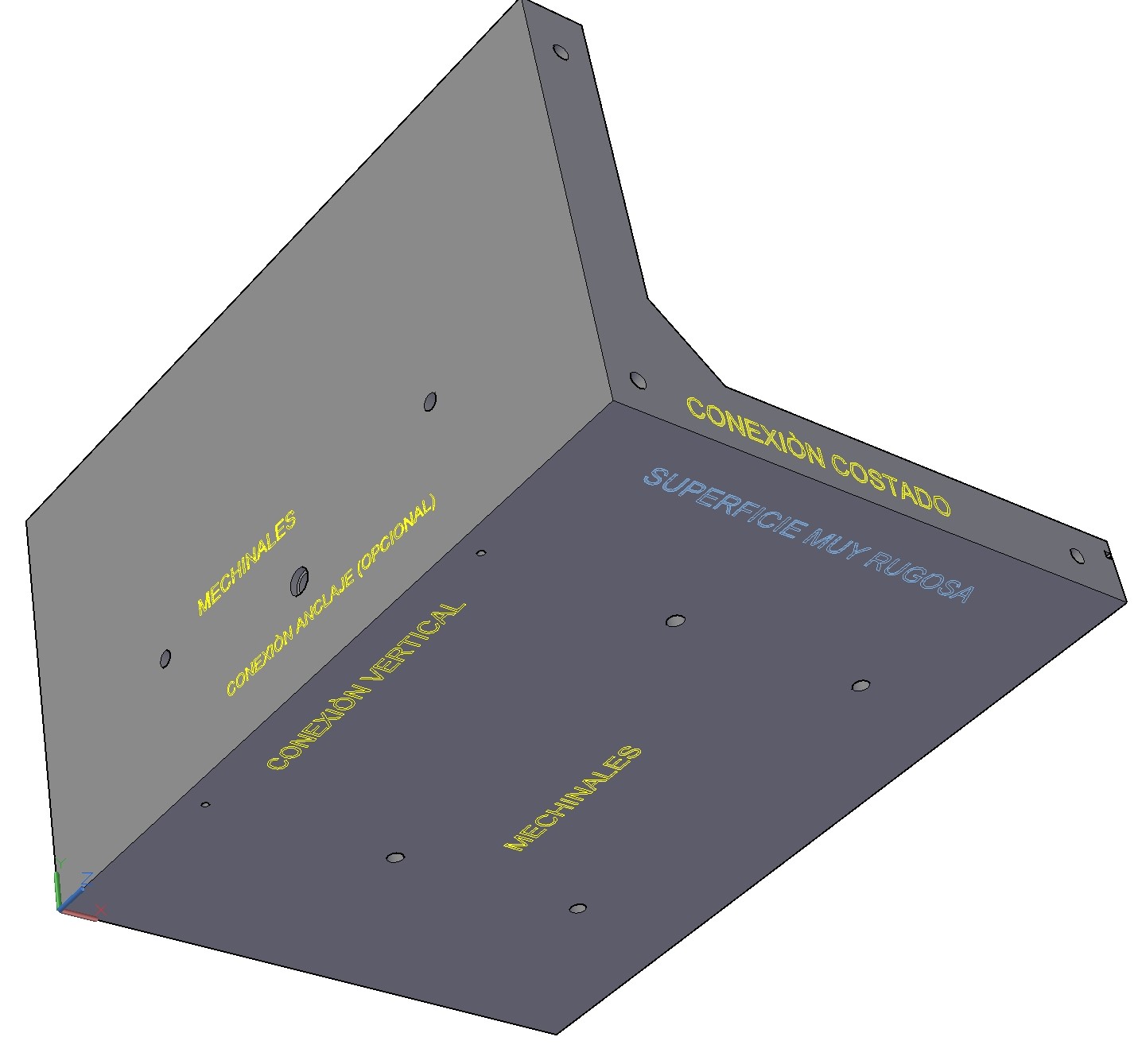
View of the MC®, where we appreciate the holes for the drainage and the connections on the sides that are always arranged between them. The “special” connections are optional: vertically (V), for geogrid (G) and for anchoring (A).
The MC® will be made of concrete reinforced with synthetic macro-fibers with structural behavior, the amount of the reinforcement and the fiber dosage are determined by the results of the calculations. In each case we will choose between three preset amounts: light, medium and strong.
The support face of the Containment Module is manufactured with small grooves in the longitudinal direction and with maximum roughness to increase friction with the underlying floor.
In all cases, a strip of draining geotextile must be provided on the joints between MC and on the walls in the wall, to prevent the material from escaping.
The MC® is placed supporting its base on an esplanade previously made with granular crushing material that ensures and improves the support, friction and drainage.

The MC® works together with the land it contains and to obtain all the necessary guarantees for its implementation, the system has been tested through analytical and simulation methodology for a large number of cases in various situations. These results are collected in the Systematic and Comparative Study using finite elements on the CM. In general, in all cases where the comparison proceeds (it is not possible, for example, with a vertical wall) there is a significant increase in the Sliding Safety Factor when using MC® that ranges between 20% and 90%. In each real case and based on a series of topographic, geotechnical, etc. data, the Mitlan technical team will write and deliver the appropriate Action Project that will contain a Justification Calculation Report.
Mitlan will be responsible for carrying out all the monitoring and quality control both in the project phase and during the execution of the work and subsequent monitoring.
We work closely with Prefadhor-Tubyder, as a company responsible for manufacturing MC®. The Quality Department of the aforementioned manufacturer is equipped with all the necessary means for the realization of the appropriate controls from the reception of the raw materials to the completion of the product, through the preparation of the concrete, placement of steel, etc.
If we achieve the equilibrium of an MC® alignment, this fixation will transmit a stabilizing component upstream in the whole of the supported ground (embankment, dismantling, etc.) that will result in a significant increase in the safety coefficient when sliding anywhere. of the contained ground.
In addition, it should be noted that due to the confinement to which the lands are subjected with the use of MC®, two important advantages are obtained:
- During execution, more compaction is acquired with less energy applied.
- Better behavior in the face of dynamic loads caused by traffic and vibrations (rail traffic, etc.).
The modules can be grouped in various ways depending on the type of solution sought for each problem:
- Attached and connected laterally by its sides forming a straight or curved alignment, a fact that occurs in all cases.
- One on top of the other to form a wall of greater height.
- Faced two by two.
- On staggered slopes forming terraces, etc.
The drainage of the infiltrated water in the contained land is carried out by the joints between MC® and by the holes arranged on the horizontal and vertical faces, covering these elements with a draining geotextile in the area of the wall to prevent the material from escaping. In addition, the pieces must rest on a regularization layer of filter material that deflects the current lines towards the lower zone.
The importance of the drainage of the whole and of each of the parts, to prevent the action of water pressures on the wall (relieved by the mechanics of the wall and joints) and on the underside of the base (solved by the holes of the base and the joints when equalizing the pressures of the water in the upper and lower faces of the own base) that the infiltrated water can cause.
In the above, we have considered the work of the MC® in 2D, taking into account the forces acting in a cross section and thinking about permanent actions.
If we talk about real problems, that is, in 3D and in extraordinary situations, the loads transmitted by the ground is presented in practice, acting according to bulbs located with a very high value of the mentioned tension in its central area, being necessary to reduce it, distributing the load with the adjacent modules and for this it is mandatory that the MC® be connected to each other by the side, in order to distribute the acting forces on more surface.
This fact allows the aforementioned pressure bulb to be transmitted to the support in a much softer way and ultimately with lower tensions, and so the support will already be able to withstand.

On the other hand, we will say that the MC® can have a very diverse and versatile use as an element that provides containment and stability in civil works: embankments, clearings, widening of roads, vertical walls, correction of landslides, increased bearing capacity, railways, channeling of rivers, dam construction, breakwaters, underground excavations with special parts for “drives”, etc.

Learn about the advantages of our modules for ground containment foundations
ADVANTAGES
-TECHNICAL ADVANTAGES
Very complete solution / Land Self-Confinement
- Very complete solution because it blocks horizontal and vertical thrusts together which produces a self-confinement of the terrain.
The connections between MCs allow a “distribution” of the acting loads.
- The existing connections between the pieces produce a solidary work with their adjacent ones, which allows a “rolling” or redistribution of the loads transmitted to the support.
Automatic operation
- The Containment Module has an “automatic” operation, the more ground pressure is exerted on it, there is more vertical component of it and therefore a greater stabilizing friction of the MC® with the support.
Ideal support to accommodate the efforts transmitted by anchors and geogrids
- The MC® is an ideal support to receive the efforts transmitted by anchors and geogrids, complementing and thus enhancing its resistance, with a reduced cost.
Longitudinal and transverse drainage
- We form a system that allows the correct longitudinal and transverse drainage of water from both terrain and infrastructure.
Comprehensive quality controls
- Being prefabricated, the MC® pieces are subjected to exhaustive quality controls, ensuring their proper operation.
Special retaining walls for curved sections
- Solution for the problem of curve tracing as we form special MC® with the trapezoidal base for easy fabrication and placement.
Reduced time limits
- Due to the ease of placement we carry out the works in a short time.
Versatility
- Due to its versatility we find solutions to difficult problems to solve using current techniques. As an example, we can cite:
- Elevation of the slope to avoid muddy problems on the road without the need for expropriation.
- Stepped slopes to save strong heights safely.
- Possibility of shaping with a set of MC® arranged in a timely manner to a stepped downpipe for breaking the hydraulic load of a given pipe.
- We can arrange them in the banks of a stream to protect them from erosion. Etc.
The variety of sizes optimizes solutions
- The wide variety of sizes that MC® can adopt allows us to optimize certain solutions in containment.
ECONOMIC ADVANTAGES
Minimum production costs
- Production costs of the Minimum Containment Module because it is a prefabricated piece of very simple geometry and there are molds prepared for all variations: straight or curved pieces, change of thickness and dimensions, all types of connections, etc.
Ease of placement
- Due to the ease of placement we carry out the works with reduced time, labor and machinery, with the consequent savings.
Cheaper embankments
- We execute cheaper embankments by arranging a line of retaining walls at its base, which allows the slope to be tilted further without lowering the safety factor and reducing the material used.
Performance without service conditions
- Performance without affecting the service in case of railway or road embankments, both for the standard execution procedure and for the driving procedure (under study), with the consequent economic savings.
Manufacturing of retaining walls on site
- Possibility of manufacturing the retaining walls on site (under study), through the use of formwork molds of the piece, reducing transport costs and time.
Decrease in space required
- Reduction of the space needed to be occupied by embankments or clearings, with the consequent reduction in costs due to excavations, material and expropriations.
- The wide variety of sizes that MC® can adopt allows us to optimize and therefore reduce certain solutions in containment.
We design different types of prefabricated retaining walls adapted to each situation.
Roads – Road widening
In this illustration, we see how we proceed to widen an existing road using an MC® line with three important advantages:
- We achieve that the contact between the existing road and the widening, typical of this type of works, is not marked afterwards, due to the great compaction derived from the confinement to which we submit the filling between the pieces and the current road.
- With the inclusion of the MC® line, we gain space in the plant to carry out the aforementioned expansion and we can work in the public domain strip of the road, thus avoiding the need for expropriations.
- The base of the widening embankment is protected by the Modules line and also the vertical external part of it, when necessary, will form part of the covered gutter.

Some more examples
In general, the same way of acting can be worth in other cases as in the following two examples:
- Provision of new entry and exit lanes at existing intersections.
Case of an adjacent embankment with installations of pipes, cables, coaxial, etc; With security guarantees we can arrange a line of MC® bordering these facilities that apart from serving as boundary delimits and clearly separates the new works to be executed.
VERTICAL WALLS
This time we have a vertical wall made up of two superimposed MC® lines. The joints are arranged “counterbalanced” and vertical and lateral connections between parts are used to enhance the distribution capacity and thus reduce any stress concentration in a given area.
The wall is not a rigid element but a group of interconnected. The stability of the set is based on that of each module and if under any circumstances there is an overload of actions on a certain MC® that breaks its balance, it will rely on the elements that surround it to restore its fixation.
In this case, the geotechnical-structural calculation necessary to reach optimal solutions is even more relevant.

To resist the thrusts
The size of the pieces, their base/height ratio and their thickness, depends on the height of the land acting on them.
When the wall is very high, both horizontal and vertical thrusts increase considerably:
- To cope with horizontal thrust we can complement the MC® lines with geogrids with high tensile strength that are connected to the internal front face of the support base of the piece. As an alternative, anchors can be used that would be anchored. (These add-ons are under study for imminent implementation).
- To counteract vertical forces, we will have a secure enough support to support the MC® We will use as foundation of the mentioned line and in increasing order of bearing capacity: breakwater layer, mass concrete, etc.
Lastly, to review the importance of the whole drainage and of each of the parts, to prevent the action of water pressures on the wall and the sub-pressures on the underside of the base that infiltrated water can cause.
DISASSEMBLIES
As seen in the image, the MC® is arranged to contain a slope, using in this case the wall to form the external part.
The MC® can be used both in new construction and conservation work.
If the slope is high, we can place several lines of MC®, arranging the pieces in a staggered way forming terraces.
In case of slope movement
If, despite the performance of the MC® line, a slope movement occurs at a certain moment, its effects will be minimized:
- In any case, the movements are more limited.
- The road will be preserved from the invasion of material, avoiding or reducing undesirable consequences such as the appearance of mud on the road.
- Finally, taking into account the distribution effect of the MC® line, the movements induced by the slope will be limited and the road condition will be reduced.
For new construction
If we refer to new construction, the most advisable once the track has been cleared – and as a consequence the rheological movements of land readjustment start up – is to arrange the Modules line at the base as soon as possible, as follows:
- Timely excavation is carried out by layers to place the MC®.
- We have drainage systems, where appropriate support improvement, regularization layer, etc.
- We place the parts properly connected.
- We proceed to fill the back of the Modules line compacting it well against the over-excavation that had been executed for placement.
The improvements of this performance are varied:
- From the first moment, the natural resistance of the slope is complemented, which now has the base of MC® as a support foot to establish its overall resistance.
Once the MC® line is fixed, the slip safety coefficient is increased at each of the points of the contained slope.

Embankments
As we can see in the image, it is an arrangement to contain a high-rise embankment from the base, the MC® line must be placed on a regularization layer of crushing granular material to increase friction and improve drainage.
The pieces receive an important load that they distribute to the support which must have sufficient bearing capacity to absorb it. If this were not the case, it would have to be improved by placing a subbase of gravel, breakwater, etc.
In extreme cases with a lot of vertical load and a weak base we can use a concrete run layer close to the line of the pieces.
Connections between parts
It is important to make the relevant connections between the pieces on the sides, especially to deal with the extraordinary actions focused on a specific area:
- In this way, the pressure bulb that occurs in this area is subjected to a reduction or “distribution” by the interconnected line of MCs that significantly reduces the final pressure acting on the support.
- Ensuring that said support resists vertical tension once the load is distributed, the MC® is attached, and generates a fixing upstream on the embankment that results in the increase of the safety factor at all points of the same.
Fix an embankment
We fix an embankment by arranging one or several lines connected vertically between them at the base of the same and adding or not another line at half height. The calculation determines in each case the most appropriate option.
A fixed embankment has controlled deformations. In this way, we ensure the maintenance on a track with the passage of time of the “initial mathematical grade”, which directly affects the conservation of safety and comfort levels in the aforementioned way, also leading to a significant saving in costs of maintenance.
What is expressed in the previous paragraph becomes more relevant when the slope of the road or esplanade has very narrow margins for its movements (example: in railways, precision foundations, etc.).
STEPPED WALLS
If we have several lines of MC® at different heights as terraces, we can overcome large slopes with a visual impact that is not very aggressive.
In the intermediate slopes that remain between the pieces, we can arrange landscaped areas as they appear in the figure.
This type of action opens a range of aesthetic possibilities and very wide and proper design to project urbanizations in very undulating terrain. Plant species, especially trees, will contribute with their roots to strengthen the embankments.

Other applications
With the same standard arrangement but placing a medium-sized breakwater on the surface of the slopes supported by its foot on the upper edge of the wall of the MC® lines, we obtain valid solutions for river canals.
The breakwater will control the erosion of the margins in these cases, while the MC® lines are responsible for constituting the skeleton that supports the entire assembly.
LANDSLIDE CORRECTION
The vertical screens or walls formed by one or several MC® lines are used to secure an embankment or dismantle in an unreliable area or redo it if necessary, a slip has already occurred or is marked, in this case we must wait to act at the most favorable situation possible.
The area prone to landslides will now have a much greater safety factor than it had.

Execution Phases
- First, we place the two side pieces that are at the height of the platform. Then we place the next two in a layer at a level below and fill immediately. Then, we have the remaining two of this group that will now be at the height of the platform. So far we would have on each side four pieces on the surface and two at a lower level. These six pieces on each side, already provide a significant support that will allow us to continue with the replacement work.
- Later, we excavate to place the four central pieces located at two levels below the layer of the platform and fill up to make up with its upper part. Then, we place on top the four pieces that correspond to a lower level and fill in the same way until it is made up and finally we place the four pieces that will go on the surface and finish the filling properly forming the slope that has to rely on the MC® surface cited. The pieces will all be connected vertically but the connection on the sides in this case will only be established on the first level for security reasons. In addition, at the lower levels there will be passive earth thrust once the excavated material for the placement of the pieces has been replaced.
- Finally, we let some days pass by watering and compacting the repaired embankment so that it stabilizes completely, thus being able to extend the upper layers of firm and rolling affected.
RAILWAY ROADS
Everything stated in the previous sections for road works is perfectly applicable for Railways or Large Irrigation Canals. In relation to this issue and in general we can say that the roads have slopes that are measured in percent, the railways in as much per thousand and the canals in as much as ten thousand. This statement implies that the obligation to maintain the initial mathematical grade in every linear work is becoming increasingly difficult due to this growing order: roads, railways and canals.
RIVERS
The MC® have a very advantageous and complete use when used for channeling streams and rivers providing a line at the base.
- With the aforementioned stepped arrangement, but placing medium-sized breakwater on the surface of the slopes supported by its foot on the upper edge of the wall of the MC® lines, we achieve optimal solutions for river canals.
- The aforementioned breakwater will control the erosion of the margins in these cases, while the MC® lines are responsible for constituting the “skeleton” that supports the entire assembly.